
About the Badge
The 2019 Saintcon badge was inspired by the Enigma machine. It was designed by myself (@compukidmike) and @_bashNinja
Design
The badge shape is a section of an Enigma rotor. A rotor has 26 notches and each badge represents one of them. There are connectors on the left and right edges to enable linking between badges (more on that later).
We used bits of the enigma drawings from http://enigma.hs-weingarten.de/download_drawings.php
The badge is composed of 2 stacked PCBs to protect the electronics, held together with beautiful brass screws. The top board is 4 layers and features a curved 16×64 RGB LED matrix on the front. It’s driven by a Lattice ICE40HX1K FPGA. This communicates with the main microcontroller via SPI. The bottom board contains the STM32L433 microcontroller along with the 26 buttons and 26 RGB LEDs for the lampboard. The 1500mAh LiPo battery is sandwiched between the boards to keep it protected. There are a total of 1051 LEDs on this badge (16×64 matrix + 26 lampboard + 1 charging indicator)!

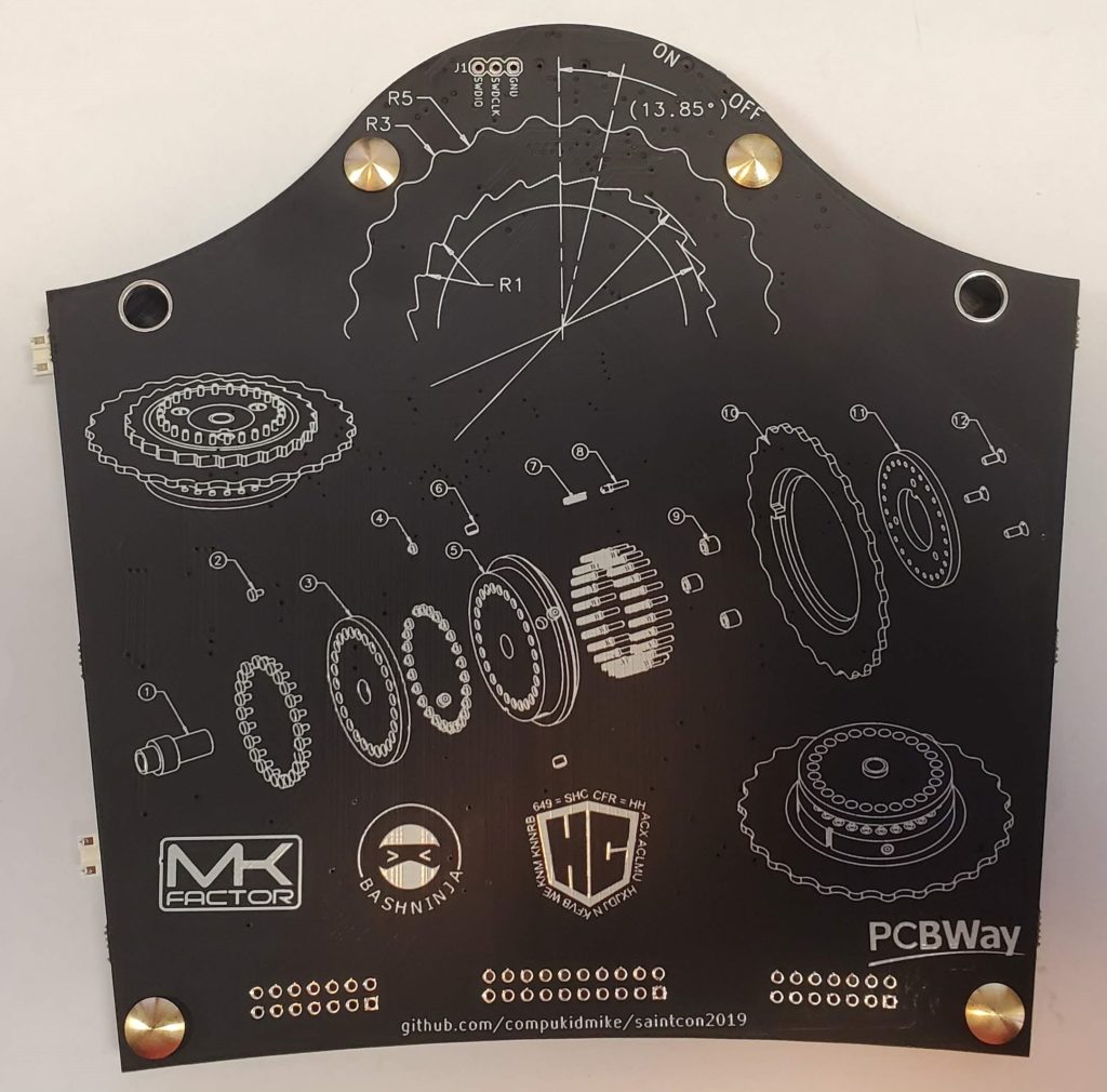
Bottom Board Inside 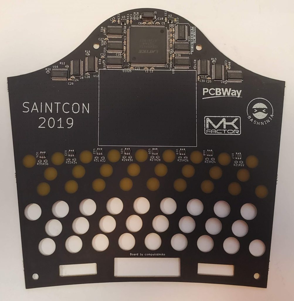
Top Board Inside
FPGA
All those LEDs need something to drive them. The basic circuit uses shift registers and row drivers, but how do you feed them data fast enough? FPGA to the rescue! Field Programmable Gate Arrays are great at parallel processing. In this instance, the FPGA drives the led matrix extremely fast to allow full color at over 30fps. It can go much faster, but ghosting becomes an issue at higher speeds.
I used Icestudio to develop the FPGA program. It’s a great open source toolchain for the Lattice ICE40 series FPGAs. The best part about it is the graphical interface that allows you to visually connect verilog modules. It makes it really easy to see the flow of your program.
The ICE40HX1K FPGA on the board has dual-port RAM which makes it really easy to implement a framebuffer. The microcontroller sends frames over SPI, which are loaded into the RAM. The FPGA then pulls the data out of RAM to display on the LED matrix. It uses Binary Code Modulation to provide dimming. The LED matrix design is very similar to common LED panels that can be purchased. This makes driving it very similar, and I used these examples to help.
The FPGA actually determined the microcontroller that was used on the badge. I used the FPGA loading code from the BlackIce-II project. I went with the same microcontroller to make development easier, and it happened to fit our requirements. We actually used the higher pin count version and used every pin on the microcontroller!
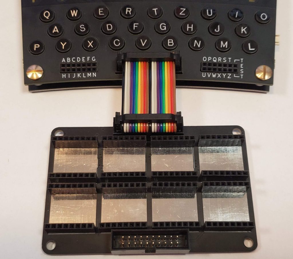
Minibadges
There are 3 connectors at the bottom of the badge. The left and right connectors represent the Enigma plugboard. Every badge came with 10 wires to enable connecting the plugboard according to the code sheet. The middle connector is for attaching minibadge holder boards. First introduced in 2017, minibadges have become a major part of Saintcon. The conference itself, as well as attendees and even vendors create minibadges to hand out to attendees. It’s a great way for people to get their feet wet with making circuit boards since you don’t have to deal with batteries/power supplies. This year we introduced minibadge holder boards. This is a separate board that hangs off the bottom of the badge. One of the goals is to enable attendees to use the same boards for future years. It takes a decent amount of time to solder a bunch of 8-pin headers and this way attendees can use the same board for future years. We also introduced individual power control for minibadges. Each board has an I2C port expander, allowing flashy patterns with the minibadges. Up to 8 of them can be chained with individual control.
Badge Challenge
This year’s badge challenge was designed to encourage attendees to work together and help each other. The story began with each attendee receiving an “intercepted” Enigma code sheet and then linking badges with their fellow “Agents” to receive instructions.
If you look closely at the code sheet, you may notice that the rotors go up to IX. We created our own rotor so that attendees couldn’t use an online enigma solver on the messages.
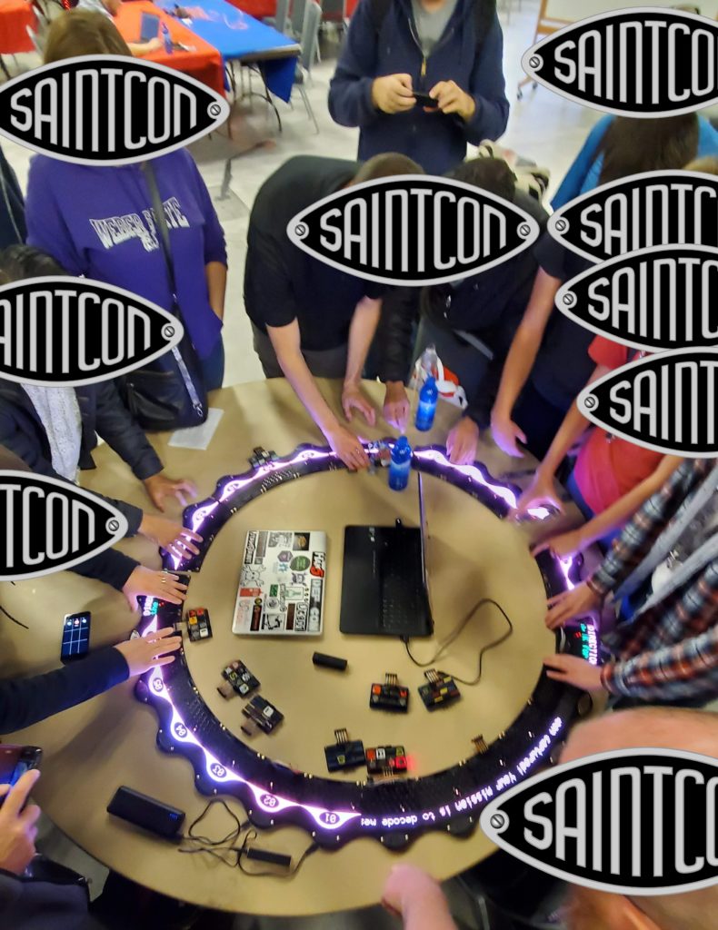
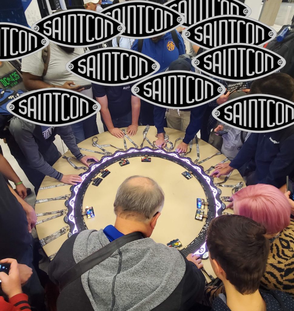
After connecting a ring of 26 badges, they were instructed to get intercepted messages at Hut 6 and decode them using their Enigma machines.


The first ring message during testing
Hut 6 refers to Bletchley Park. This was the hut where intercepted radio messages were delivered to the code breakers. At the conference, there was a station set up with a “teleprinter” where Agents would connect their badge and receive the next intercepted message for them to decode. We used an old dot-matrix receipt printer for our “teleprinter.” It was very well-received and you can’t help but enjoy the nostalgic sound of a dot-matrix printer.

Me at “Hut 6”. Sadly we didn’t have time to finish the badge ring, but it still looked awesome. 
An Agent is connecting their badge to receive a new message
After decoding a few messages, Agents were instructed to form another badge ring, but this time they required a Commander to join their ring. Commanders were members of the Saintcon Committee, and their badges had special code that would give the Agent badges a new message and further instructions. There were multiple reasons for this game mechanic. One was so that the messages could only be received from the ring, and not by dumping firmware. The other was so that we could be part of the badge rings (it’s really fun for us to see everyone working together, and we also had prizes for the first ring to complete the challenge).
Commander badges had special emblems so that Agents could identify them. The brass emblems were etched with ferric chloride, then painted and sanded.
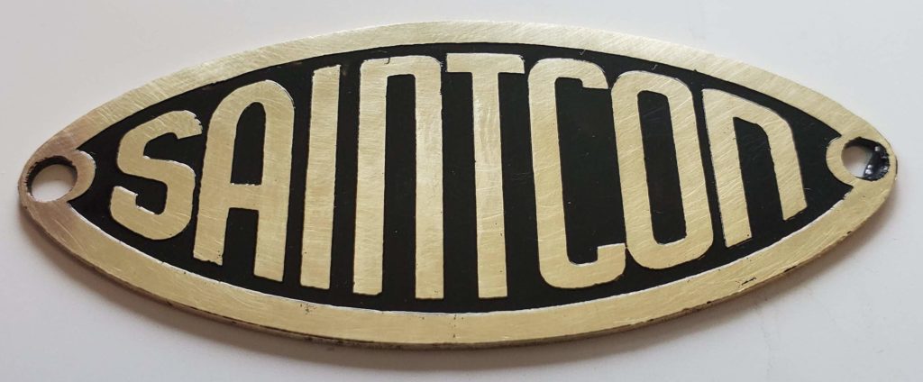
Finished Emblem 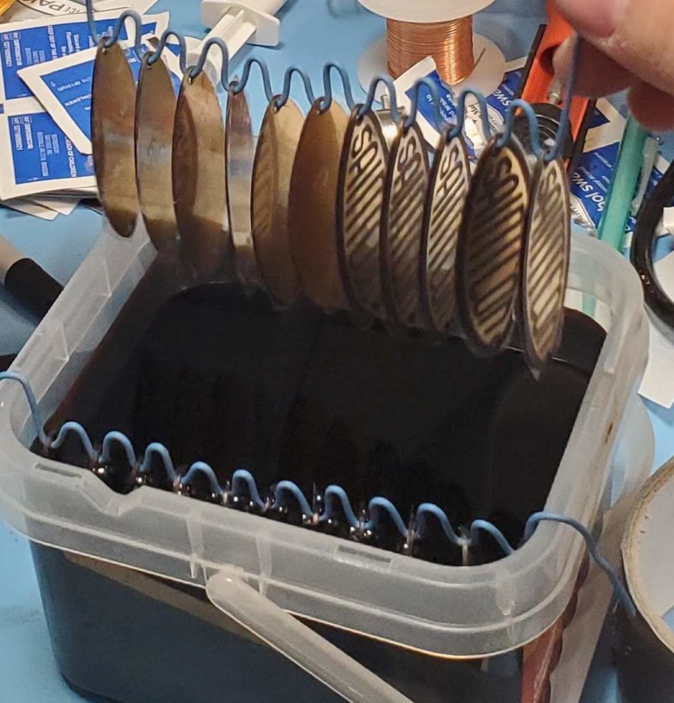
Going into etching solution 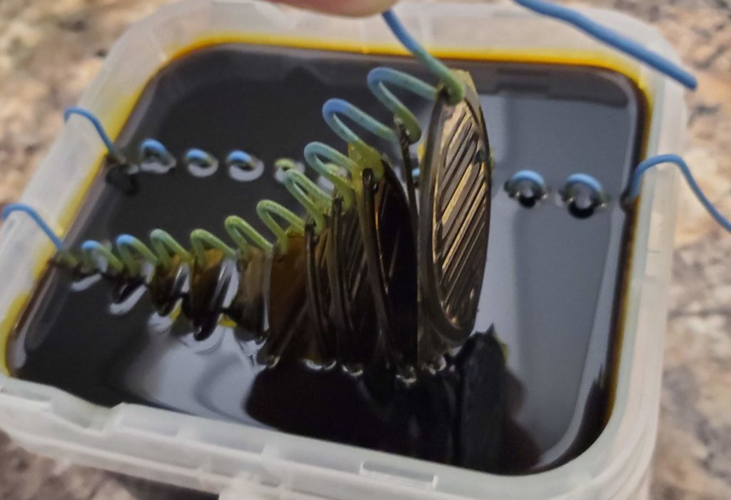
Finished etching 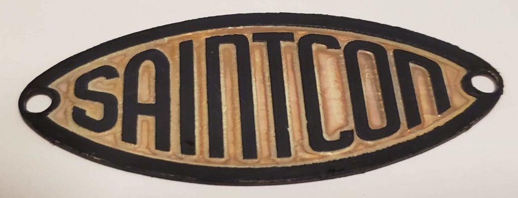
Cleaned after etching 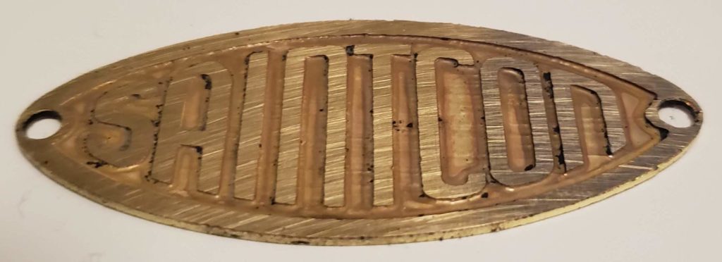
Etch resist removed
One of the best things about the badge challenge was watching attendees work together. Since they all had to be a minimum level to move on, everyone was helping others with the challenge. Helping others helped them get enough people on the same level so they could all level up. Even after finishing the challenge, it was great to see some attendees sticking around to help others finish it.
Badge-to-Badge Connectors
We searched far and wide for connectors that would work for connecting the badges together. We didn’t want the issues that happened at Defcon 26, but we still needed a cheap connector. In the end we went with these 2-pin lighting connectors. They’re used in things like LED TV backlight boards. We did have a few that got ripped off the board, but overall they worked well. However, there was a board production issue that prevented them from working as well as they did on the prototypes…
Production rails are sometimes added by the factory to enable a board to go through the pick and place machines. This is especially true if the board shape isn’t a rectangle. The rails are connected by “mousebites” and enable the rails to be snapped off after assembly. I hadn’t considered the effect this would have on the badges. The rails were attached at the sides where badges would be connected together. They don’t snap off very cleanly, and it leaves little ridges. This meant the boards couldn’t fully connect, and there was a ~1-2mm gap. The connectors would make contact, but it was flaky. Unfortunately this caused a lot of problems for attendees who were trying desperately to get 26 badges to stay connected in a ring. The tiniest movements could cause the whole thing to disconnect and require realignment. However, they persevered and were rewarded with a new ring message and progressed to the next level!
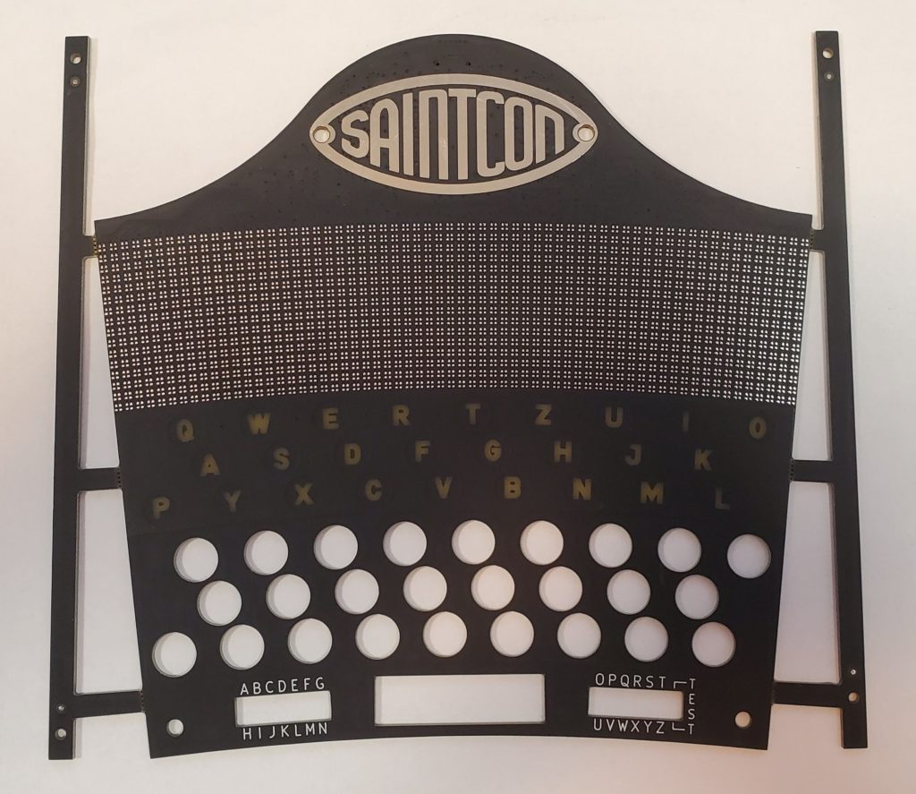
Rails on Board 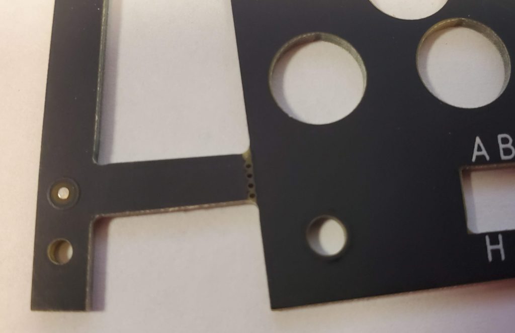
Rail Connection 
Mousebites after removing rail
Board-to-Board Connectors
With the LED matrix and FPGA on the top board and the main microcontroller on the bottom board, we needed a good connector between the boards. We used BergStak connectors from Amphenol. They offer a bunch of different heights and they worked great for this application.
Firmware
Most of the badge firmware was written by @_bashNinja and myself. Due to delays (more on that later), we had some help at the end. @Sodium_Hydrogen and @risenrigel jumped in to help us during the first day of the conference. We cannot thank them enough!
We’d also like to thank all the attendees who were very forgiving with the firmware issues. They had to reflash their badges no less than 4 times to complete the challenge! Nevertheless most of them were happy and enjoyed the badge challenge!
We had grand and glorious plans for the badge firmware. In the end we implemented about 50% of it. We still ended up with a fully functioning Enigma emulator, the badge challenge worked, attendees could display custom messages, and everything worked fairly well. We wanted to have actual ring message animations. We ended up just displaying the message and it worked well enough. We also wanted more games and more animations to take advantage of the RGB LED matrix.
There were some concessions made on software features and badge challenge specifics due to the short time we had. I talked about the Commander badges sending the messages around the ring, but that ended up changing. In the end, we did send the messages around for display, but the individual badges already had the messages on-board. There were issues with saving the messages on the individual badges. Since the microcontroller doesn’t have actual EEPROM, we used an EEPROM emulation library from ST. There are some issues with it, though we’re not sure if it’s the library or our implementation causing the issues. In any case, we didn’t have time to properly debug it. So we only save the badge challenge level in EEPROM and the ring message is already stored in flash. Even so, there are still issues with EEPROM corruption. If you save the Custom Message over and over, you will fill up the emulated EEPROM and it gets corrupted. At that point, the badge resets and your challenge progress is lost. Thankfully that didn’t happen very often. I did end up creating a workaround that would allow me to jump people through the challenge levels quickly so that I could get them back to where they were.
Another place where we took a shortcut due to time was with the printed messages. The badge transmits a 6 character code to the printer which is unique to each badge and different for each challenge level. The printer should append this code to the end of the “intercepted” message so the badge can check to make sure the message was properly decoded. Since we ran out of time, we ended up just adding the characters in plain text at the end of the message rather than encoding it (There wasn’t time to add the enigma code to the arduino running the printer). This meant that even if Agents didn’t decode the message properly, the badge would still “level up” if you typed in the end of the message. In fact, you only had to type in 9 characters total including the last 6 characters. Luckily only a few attendees figured this out, so it didn’t ruin the challenge.
Scope Creep
This whole idea started last year at Saintcon. I was talking with @saintjup1t3r (head of Saintcon), and he said “wouldn’t it be cool if we had a badge that would connect in a ring and we had a circular display.” He was impressed by the LED matrix on the @CarHackVillage badge from @defcon that year, and wanted something similar. And thus the Saintcon 2019 badge was born. Then the enigma theme was added, and then it just got out of control. We ended up with an amazing badge, but we definitely suffered from scope creep.
Budget
We had an initial budget of $50 per badge (Spoiler: we blew the budget…). We ended up with a cost of $53 when we ordered everything (again, scope creep). There were other little things that got added on during production (extra shipping costs, board testing, etc), but the biggest thing that blew the budget was tariffs. When our pcb assembly house was shipping the boards, they asked us how much to declare for customs. Since we’re a non-profit org and our financials are all shared openly, we didn’t feel right fudging the numbers here. Our costs for the boards were ~$50k, and we got hit with a 25% tariff. We paid ~$13k in tariffs. That bumped the cost per badge up by $10, so we really blew the budget this year! All said, we were probably close to $70 per badge.
Delays
There were many delays with the badges this year. I made the mistake of taking on way too much. I created 2 unofficial defcon badges with my wife @ktjgeekmom. I also worked on @s7a73farm‘s badge, the @Hak4Kidz badge, and the @openwest badge. I also changed jobs in the middle of all this. Basically I ran out of time and we ordered the badges later than we wanted to. That said, the estimated completion date for the boards was the beginning of October. We ended up receiving them the day before the con (Oct 21st). To their credit, we had very few hardware failures. Out of 1350 badges, we had ~30 that had an issue, and most of those were small things like a single LED that wasn’t working. Easily fixable.
We also didn’t have enough prototypes to make an entire ring of badges. This was a failing on my part. I didn’t want to hand place that many LEDs (I made 3 boards by hand. It takes ~3 hours just to place all the LEDs), and a short run of ~50 would have cost a crazy amount of money. We were also supposed to get the final boards ~3 weeks before the conference. By the time we realized that wasn’t going to happen, it was too late to do anything about it. This is the main reason the firmware wasn’t complete before the conference.
Lessons Learned
- Order badges at least 4 months before the con
- Get enough prototypes to completely test every aspect of the firmware
- Manage scope from the beginning to keep it under control
- Discuss production rail breakaway points with the factory to make sure they aren’t in critical locations
Further Info
All the code and hardware info can be found on github at https://github.com/compukidmike/Saintcon2019
There is also a recording of my badge talk at Saintcon https://www.youtube.com/watch?v=MAhJ2W_oN14
Thanks
Thanks to everyone who helped make this badge happen and thanks to every Saintcon attendee who was patient with us and played the badge challenge!